THE INITIAL SELECTIONS
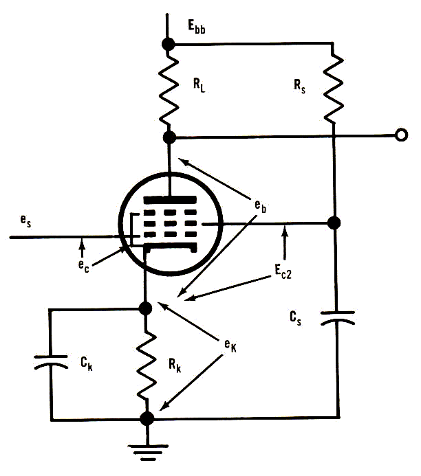
The pentode R-C amplifier
circuit is shown in Fig.3-4. Based on
this
circuit, a tube may be selected,
and then its screen voltage selected. Then
the values of plate current
may be determined and the load resistance
selected.
Fig.3-4
Basic design of a pentode amplifier.
Example 7. A
6BH6
pentode has been chosen for use with
Fig.3-4.
Assuming a 200-volt supply
and choosing Ec2
= 100 volts, the minimum
plate voltage is 75 volts,
giving the voltage ( maximum ) across the load
resistor RL
as 125 volts. To minimize the grid current, assume that the
positive limit grid
bias is -0.5 volt. From the G-Curve the
nominal
plate current
Ip = 7.0 ma at the
minimum bias. Since eb/Ec2
= 0.75,
the value of Xp
is 0.95 and the corrected plate current is 6.65 ma ( see
page
2 ). Therefore, the load resistance is 19,000
ohms - actually an
18,000-ohm resistor probably
would be used.
If a bias excursion
to zero bias can be permitted, then Ip
= 9.3 ma
and, with eb/Ec2
= 0.75, Xp =
0.95. Then ib
= 8.83 ma, giving RL
as
14,150 ohms. A standard
15,000-ohm resistor would be used.
16
Copyright 2008 for Phyllis
K. Pullen, M.D.,
by Robert J. Legg