|
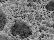
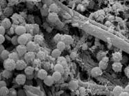
Similar to photographs, SEM micrographs show 3-dimensional structures through 2-dimensional images. Thus, yeast cells and bacteria in a kefir grain (Fig. 1), the protein matrix of a set-style yogurt (Fig. 2), or microorganisms on a composted plant leaf (Fig. 3) appear at a relatively smooth level.
 |
 |
 |
| Fig. 1. Surface of a kefir grain consists
of large yeast cells and smaller bacteria. |
Fig. 2. Yogurt microstructure consists of
branched chains of milk proteins and globular void spaces. |
Fig. 3. A composted plant leaf is covered
with fungal hyphae and spores. |
Basically, two images obtained at angles differing by 6° to 12° are needed to produce the 3-dimensional effect. Such images may be laid side by side and viewed through a simple
optical stand (Fig. 4). To better explain the microstructure of some dairy products such as yogurt and cheese curd, stereograms of this kind have been used in scientific papers, e.g., ruptured milkfat globule membrane, Fig. 4 in M. Kaláb: Artefacts in conventional scanning electron microscopy of some milk products, Food Microstruc. 3(2), 92-111, 1984. Mucilage droplets emerging from the hull of a moistened yellow mustard seed are shown in Fig. 4 in I. R. Sidiqui et al.: Mucilage in yellow mustard (Brassica hirta) seeds, Food Microstruc. 5(1), 157-162, 1986.
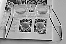 |
| Fig. 4. Optical stand for pairs of stereograms | Similar pairs of images may also be shown on a computer monitor but they may be viewed only by one person at a time and their dimensions are limited by the need to show the pair of images side by side while holding the optical stand pressed towards the monitor.
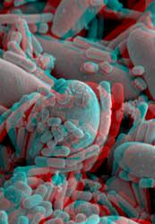
Anaglyphs, i.e., pairs of red and cyan, red and green, or read and blue stereo images within a single
frame viewed through a pair of corresponding glasses are better suitable
for the computer monitor. They may be viewed by several persons at the same time and their positioning in respect to the images is not as critical.
Searching for anaglyphs in the Google provides a large number of images and links, e.g., the explanation of what anaglyphs are and how to make them. The author of that tutorial prefers the PNG format to JPG because compression artifacts in the latter format degrade the quality of the resulting anaglyphs. There are SEM anaglyphs in science available for viewing using red-and-blue glasses. A 3D model of the enzyme deacetylase shows the configuration of a protein molecule. Some anaglyphs of micrographs are available here.
J. E. Heuser shows
membrane traffic in stereo and refers to many websites by Frank Newbold. This site consists of a large number of links to the making of anaglyphs.
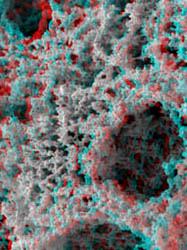
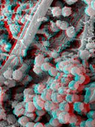
It is relatively easy to obtain and publish such stereo micrographs which correspond to Figures 1 to 3, as may be evident from Figures 5 to 7. Unlike the original micrographs, which appear in landscape format, the anaglyphs are shown in portrait format:
 |
 |
 |
| Fig. 5. The yeast cell partly covered with bacteria in the centre of the image raises out of the image plane higher up. The top of the image sinks quite low. |
Fig. 6. The matrix consisting of
branched chains of milk protein particles is not smooth around the globular void spaces but forms walls. |
Fig. 7. The fungal spores in the lower half of the image raise higher up above the composted plant leaf with fungal hyphae. |
Scanning electron microscopy
The reason for this difference is the need to obtain 2 micrographs. After the first micrograph is taken, the specimen is tilted 6° to 10° and the second micrographs is taken. Tilting is done around a horizontal axis running through the centre of the stage. However, the area of interest would lie only in very few situations directly above the axis of rotation inside the microscope, but it will be anywhere within the SEM stub. While the stage with the specimen is being tilted, the image moves on the monitor of the microscope. Thus, it has to be shifted manually to stay at the centre. At magnifications of several thousand times it may be advisable to reduce the magnification after taking the first image to 400-700x, and to mark a characteristic feature on the monitor. After the tilting is completed, it may be easier to find the particular area after the original magnification is set.
Multi-sample holders, such as the one for 7 samples holding here only 4 SEM stubs are considerably less suitable to obtain stereo pairs because the sample may move horizontally and vertically even more than 1 mm:
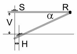 |
Fig. 8. Tilting of a sample (S) on a multi-sample holder by degree α around the axis of rotation R. The sample moves by the distance H towards the axis of rotation and by the distance V down. In order not to reduce the working distance and alter the magnification, the sample must be elevated back by that distance. |
With our eyes, we view things from the left with our left eye and from the right with our right eye. In contrast, by tilting a sample, we obtain micrographs from the top. To prepare a pair of micrographs suitable to form an anaglyph, it is necessary to open them in a graphics software such as Adobe Photoshop and rotate each micrograph 90°, both the same way either in clockwise or anticlockwise direction. If the micrographs markedly differ in brightness, it is the time to adjust them accordingly. They may be somewhat off one from another. To make them fit, copy one over the other as Layer 1 and reduce opacity of Layer 1 to about 50%. This will make both images visible. Find remarkable features and move Layer 1 over the Background to make the features match as closely as possible remembering that they are somewhat shifted one from the other. Their height from the lower micrograph edge must be the same but the width may differ. Then crop the entire image so that both images are included in the new frame. Return opacity of Layer 1 to 100%. Copy Layer 1 to make a new image and give it a new filename. Delete Layer 1 to leave only the Background and save it.
Using anaglyph software, select one image as "left" and the other as "right". Make the anaglyph and check it with a pair of red and green (or red and cyan or blue) glasses, keeping the red glass on the left eye.The stereo effect may be seen immediately. If it is not, make a new anaglyph with the images reversed between left and right.
There are various software programs available to assemble left and right images into anaglyphs. One of the free programs is "Anaglyph Maker" by Takashi Sekitani. It may be downloaded as a 729 kB anamk108.zip file. The program makes it possible to create gray or colour anaglyphs for red-and-cyan glasses, tinted red-and-green and red-and-blue anaglyphs and other images.
The Anaglyph Maker window is divided into two parts. The first step is to mark what kind of anaglyph should be created. "Anaglyph Gray (Red-Cyan)" is the default setting. Then the file of the left image is imported into the "Load Left Image" screen. With larger files it takes a few seconds. The program makes it possible to adjust the brightness and contrast of the image. In a similar way, the right image is also loaded and adjusted, if necessary.
After clicking on "Make 3D image", the anaglyph appears on the right screen. It may be saved in BMP or JPEG format. In the latter case, image quality may be selected, whereby the number 9 gives the highest quality. The saved anaglyph may further be adjusted in Adobe Photoshop or another graphics program.
Without red-and-cyan, red-and-green, or red-and-blue glasses, an anaglyph appears as an image moved during exposition or as a faulty superimposition of two shifted images. Through the proper glasses, the images show the 3-dimensional nature of the specimens. They reveal the true topography of the specimen's surface. They may also help to better understand interactions between minute particles such as thrombocytes and bacteria or magnetic beads and bacteria. A comparison of a 2D and a 3D image of fungal spores in compost, at a high resolution, is available in Figure 13 here.
Updated: April 20, 2017.
Home
©SCIMAT 2017
|